- 您现在的位置:买卖IC网 > Sheet目录255 > SZMMBZ33VAWT1G (ON Semiconductor)TVS ZENER 40W 33V SC-70-3
�� �
�
�MMBZxxVAWT1G� Series,� SZMMBZxxVAWT1G� Series�
�MAXIMUM� RATINGS�
�Rating�
�Peak� Power� Dissipation� @� 1.0� ms� (Note� 1)�
�@� T� L� ?� 25� ?� C�
�Total� Power� Dissipation� on� FR� ?� 5� Board� (Note� 2)�
�@� T� A� =� 25� ?� C�
�Derate� above� 25� ?� C�
�Thermal� Resistance� Junction� ?� to� ?� Ambient�
�Junction� and� Storage� Temperature� Range�
�Symbol�
�P� pk�
�?� P� D� ?�
�R� q� JA�
�T� J� ,� T� stg�
�Value�
�40�
�200�
�1.6�
�618�
�?� 55� to� +150�
�Unit�
�W�
�?�
�mW�
�mW/� ?� C�
�?� C/W�
�?� C�
�Stresses� exceeding� Maximum� Ratings� may� damage� the� device.� Maximum� Ratings� are� stress� ratings� only.� Functional� operation� above� the�
�Recommended� Operating� Conditions� is� not� implied.� Extended� exposure� to� stresses� above� the� Recommended� Operating� Conditions� may� affect�
�device� reliability.�
�1.� Non� ?� repetitive� current� pulse� per� Figure� 5� and� derate� above� T� A� =� 25� ?� C� per� Figure� 6.�
�2.� FR� ?� 5� =� 1.0� x� 0.75� x� 0.62� in.�
�ELECTRICAL� CHARACTERISTICS�
�(T� A� =� 25� ?� C� unless� otherwise� noted)�
�UNIDIRECTIONAL� (Circuit� tied� to� Pins� 1� and� 3� or� 2� and� 3)�
�Symbol�
�Parameter�
�I� PP�
�V� C�
�V� RWM�
�I� R�
�Maximum� Reverse� Peak� Pulse� Current�
�Clamping� Voltage� @� I� PP�
�Working� Peak� Reverse� Voltage�
�Maximum� Reverse� Leakage� Current� @� V� RWM�
�I� F�
�I�
�I� R� V� F�
�V� BR�
�I� T�
�Q� V� BR�
�Breakdown� Voltage� @� I� T�
�Test� Current�
�Maximum� Temperature� Coefficient� of� V� BR�
�V� C� V� BR� V� RWM�
�I� T�
�V�
�I� F�
�Forward� Current�
�V� F�
�Z� ZT�
�I� ZK�
�Z� ZK�
�Forward� Voltage� @� I� F�
�Maximum� Zener� Impedance� @� I� ZT�
�Reverse� Current�
�Maximum� Zener� Impedance� @� I� ZK�
�I� PP�
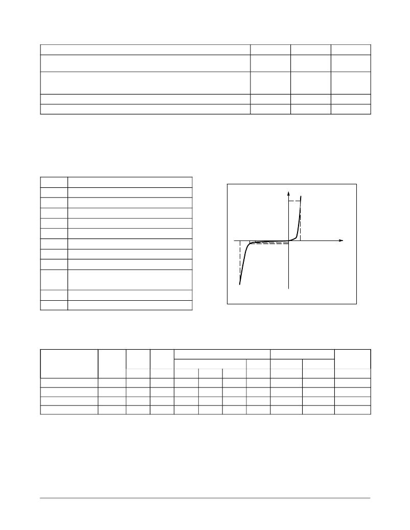
�Uni� ?� Directional� TVS�
�ELECTRICAL� CHARACTERISTICS� (T� A� =� 25� ?� C� unless� otherwise� noted)�
�UNIDIRECTIONAL� (Circuit� tied� to� Pins� 1� and� 3� or� Pins� 2� and� 3)�
�(V� F� =� 0.9� V� Max� @� I� F� =� 10� mA)�
�Device*�
�Device�
�Marking�
�V� RWM�
�Volts�
�I� R� @�
�V� RWM�
�nA�
�Breakdown� Voltage�
�V� BR� (Note� 3)� (V)�
�Min� Nom� Max�
�@� I� T�
�mA�
�V� C� @� I� PP� (Note� 4)�
�V� C� I� PP�
�V� A�
�Q� V� BR�
�mV/� 5� C�
�MMBZ15VAWT1G�
�MMBZ20VAWT1G�
�MMBZ27VAWT1G�
�MMBZ33VAWT1G�
�AT�
�AU�
�AA�
�AV�
�12�
�17�
�22�
�26�
�50�
�50�
�50�
�50�
�14.25�
�19.00�
�25.65�
�31.35�
�15�
�20�
�27�
�33�
�15.75�
�21.00�
�28.35�
�34.65�
�1.0�
�1.0�
�1.0�
�1.0�
�21�
�28�
�40�
�46�
�1.9�
�1.4�
�1.0�
�0.87�
�12.3�
�17.2�
�24.3�
�30.4�
�3.� V� BR� measured� at� pulse� test� current� I� T� at� an� ambient� temperature� of� 25� ?� C.�
�4.� Surge� current� waveform� per� Figure� 5� and� derate� per� Figure� 6�
�*Include� SZ-prefix� devices� where� applicable.�
�http://onsemi.com�
�2�
�发布紧急采购,3分钟左右您将得到回复。
相关PDF资料
SZMMBZ6V8ALT1G
DIODE ZENER 24W 6.8V SOT-23
SZMSQA6V1W5T2G
TVS ARRAY QUAD ESD 6.6V SOT353
SZNUP2105LT3G
IC CAN BUS PROTECTOR DUAL SOT-23
SZNUP4016P5T5G
TVS ARRAY ULT LOW CAP SOT-953
SZNUP4301MR6T1G
IC TVS DIODE ARRAY 70V 6-TSOP
SZP6SMB62AT3G
TVS ZENER 600W 62V UNIDIR SMB
SZSM05T1G
TVS ZENER DUAL 300W 5V ESD SOT23
SZSMF12CT1G
TVS ARRAY 5LINE 100W 12V SC88
相关代理商/技术参数
SZMMBZ4252T1G
功能描述:稳压二极管 ZEN DUAL .225W 27V RoHS:否 制造商:Vishay Semiconductors 齐纳电压:12 V 电压容差:5 % 电压温度系数:0.075 % / K 齐纳电流: 功率耗散:3 W 最大反向漏泄电流:3 uA 最大齐纳阻抗:7 Ohms 最大工作温度:+ 150 C 安装风格:SMD/SMT 封装 / 箱体:DO-214AC 封装:Reel
SZMMBZ4252T3G
功能描述:稳压二极管 ZEN DUAL .225W 27V RoHS:否 制造商:Vishay Semiconductors 齐纳电压:12 V 电压容差:5 % 电压温度系数:0.075 % / K 齐纳电流: 功率耗散:3 W 最大反向漏泄电流:3 uA 最大齐纳阻抗:7 Ohms 最大工作温度:+ 150 C 安装风格:SMD/SMT 封装 / 箱体:DO-214AC 封装:Reel
SZMMBZ5221BLT1G
功能描述:稳压二极管 ZEN REG .225W 2.4V RoHS:否 制造商:Vishay Semiconductors 齐纳电压:12 V 电压容差:5 % 电压温度系数:0.075 % / K 齐纳电流: 功率耗散:3 W 最大反向漏泄电流:3 uA 最大齐纳阻抗:7 Ohms 最大工作温度:+ 150 C 安装风格:SMD/SMT 封装 / 箱体:DO-214AC 封装:Reel
SZMMBZ5222BLT1G
功能描述:稳压二极管 ZEN REG .225W 2.5V RoHS:否 制造商:Vishay Semiconductors 齐纳电压:12 V 电压容差:5 % 电压温度系数:0.075 % / K 齐纳电流: 功率耗散:3 W 最大反向漏泄电流:3 uA 最大齐纳阻抗:7 Ohms 最大工作温度:+ 150 C 安装风格:SMD/SMT 封装 / 箱体:DO-214AC 封装:Reel
SZMMBZ5225BLT1
制造商:ON Semiconductor 功能描述:
SZMMBZ5225BLT1G
功能描述:稳压二极管 ZEN REG .225W 3.0V RoHS:否 制造商:Vishay Semiconductors 齐纳电压:12 V 电压容差:5 % 电压温度系数:0.075 % / K 齐纳电流: 功率耗散:3 W 最大反向漏泄电流:3 uA 最大齐纳阻抗:7 Ohms 最大工作温度:+ 150 C 安装风格:SMD/SMT 封装 / 箱体:DO-214AC 封装:Reel
SZMMBZ5226BLT1G
功能描述:稳压二极管 ZEN REG .225W 3.3V RoHS:否 制造商:Vishay Semiconductors 齐纳电压:12 V 电压容差:5 % 电压温度系数:0.075 % / K 齐纳电流: 功率耗散:3 W 最大反向漏泄电流:3 uA 最大齐纳阻抗:7 Ohms 最大工作温度:+ 150 C 安装风格:SMD/SMT 封装 / 箱体:DO-214AC 封装:Reel
SZMMBZ5227BLT1G
功能描述:稳压二极管 ZEN REG .225W 3.6V RoHS:否 制造商:Vishay Semiconductors 齐纳电压:12 V 电压容差:5 % 电压温度系数:0.075 % / K 齐纳电流: 功率耗散:3 W 最大反向漏泄电流:3 uA 最大齐纳阻抗:7 Ohms 最大工作温度:+ 150 C 安装风格:SMD/SMT 封装 / 箱体:DO-214AC 封装:Reel